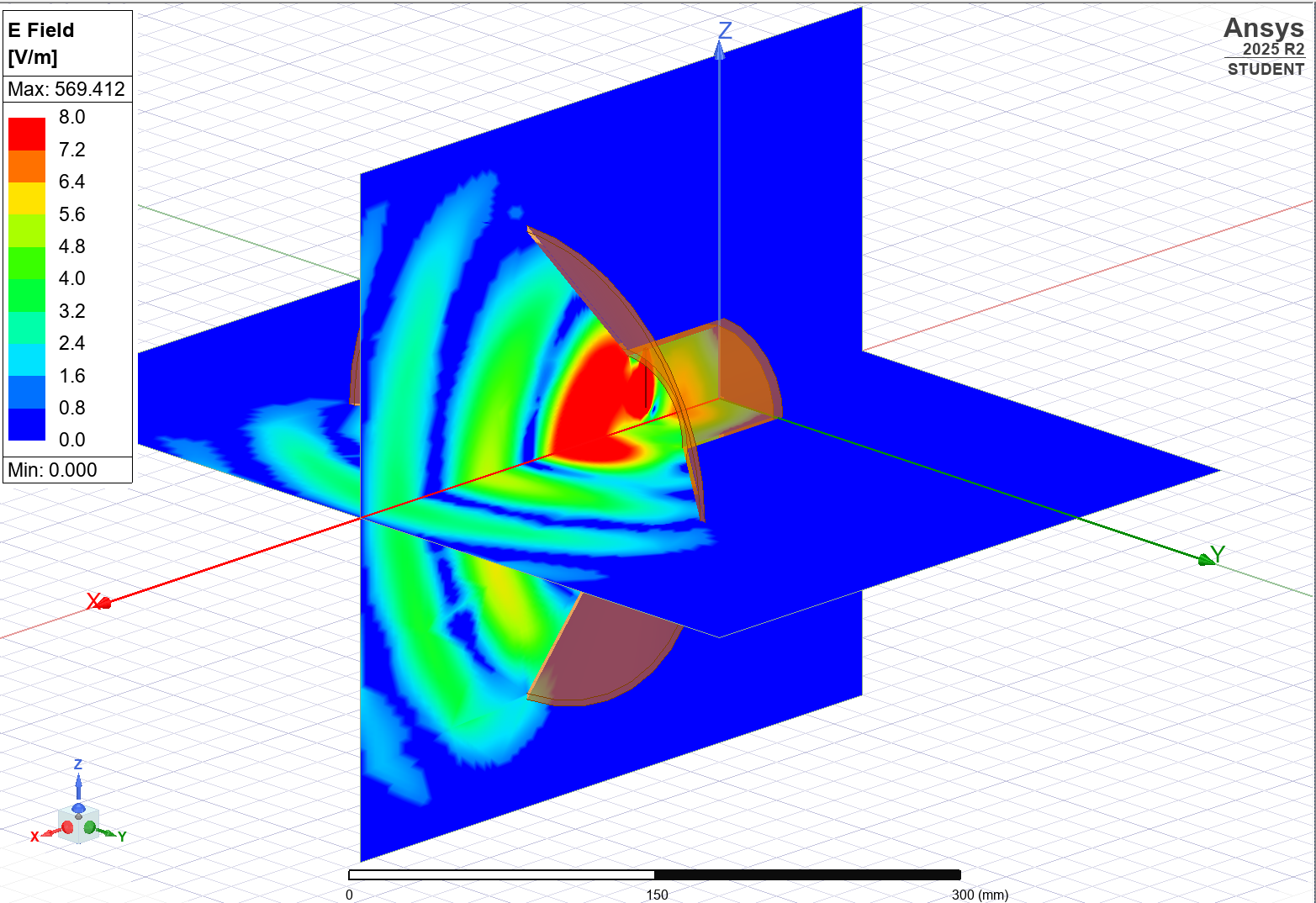
Ansys HFSS software was used to iterate the design of our horn antennas. Two configurations were used and simulated - a conical horn antenna (shown here) and an exponential horn antenna. A pyramidal horn was prototyped but didn't perform well over the desired frequency range.
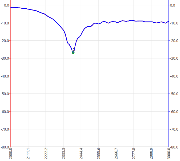
To account for manufacturing variations, I manually trimmed a quarter-wave feedline in the horn antenna to maximize power transmitted at the frequency of 2.45 GHz. This data was gathered in real time using a handheld VNA (NanoVNA V2), as shown here. S11 is on the vertical axis, in dB.
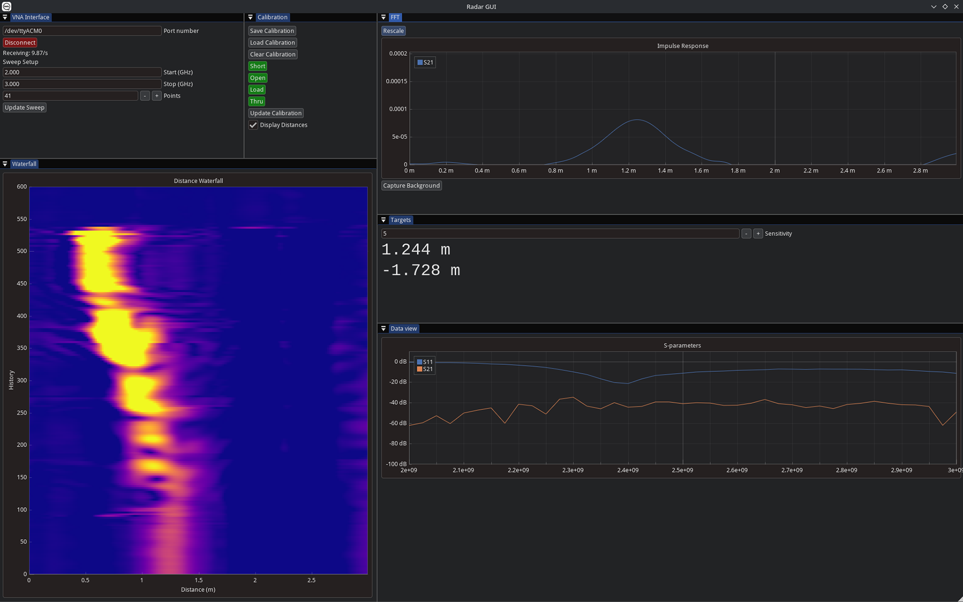
I developed a custom GUI using Dear ImGui to process and display the radar data. Key features include a waterfall diagram, impulse response and peak detection, and SOLT calibration that can be easily restored from a file. Data was streamed from the NanoVNA over serial/USB, and an inverse FFT was taken to extract the impulse response. This was used to perform time-domain reflectometry, ultimately determining object distance.
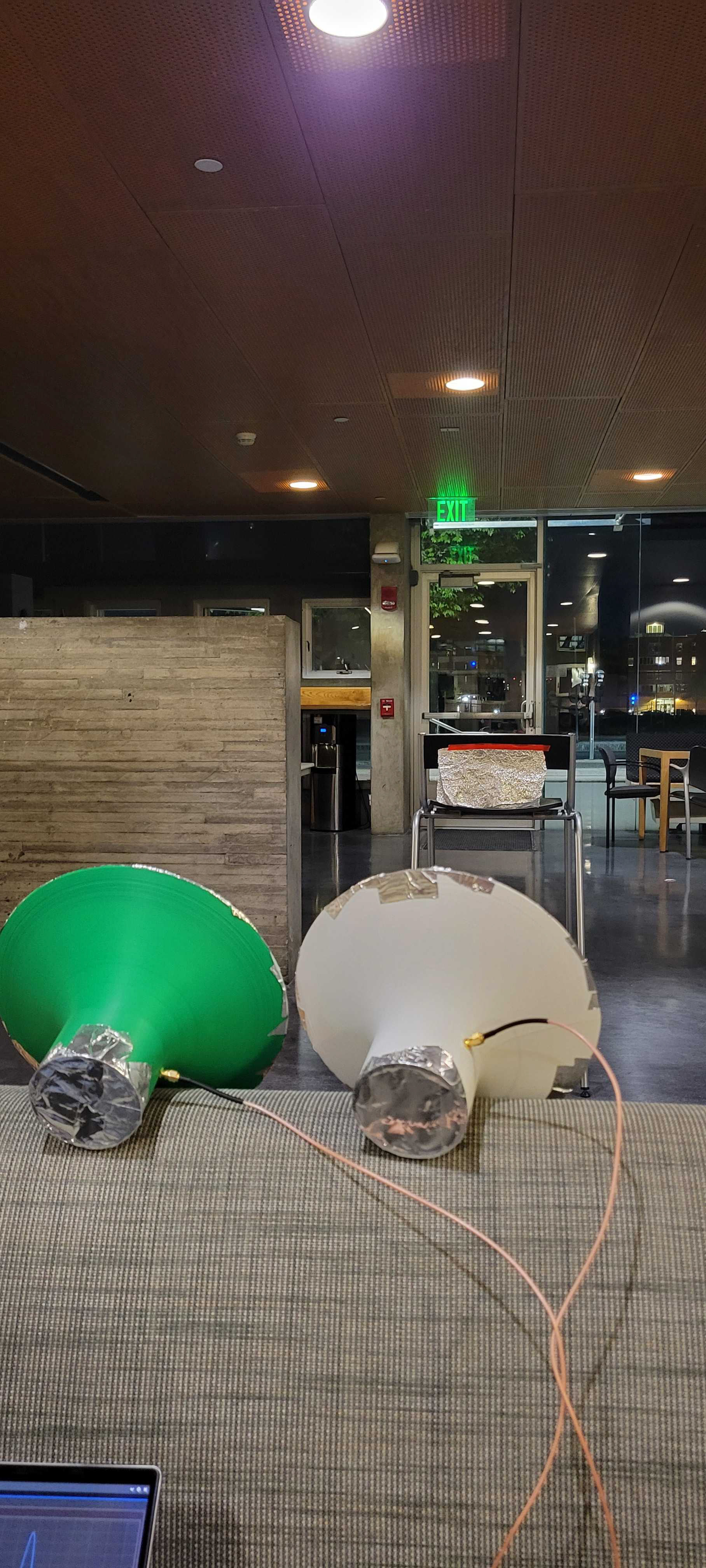
An example of the measurement setup. Here, two exponential horn antennas - one transmit, one receive - are used to determine the distance to a piece of metal foil several feet away.
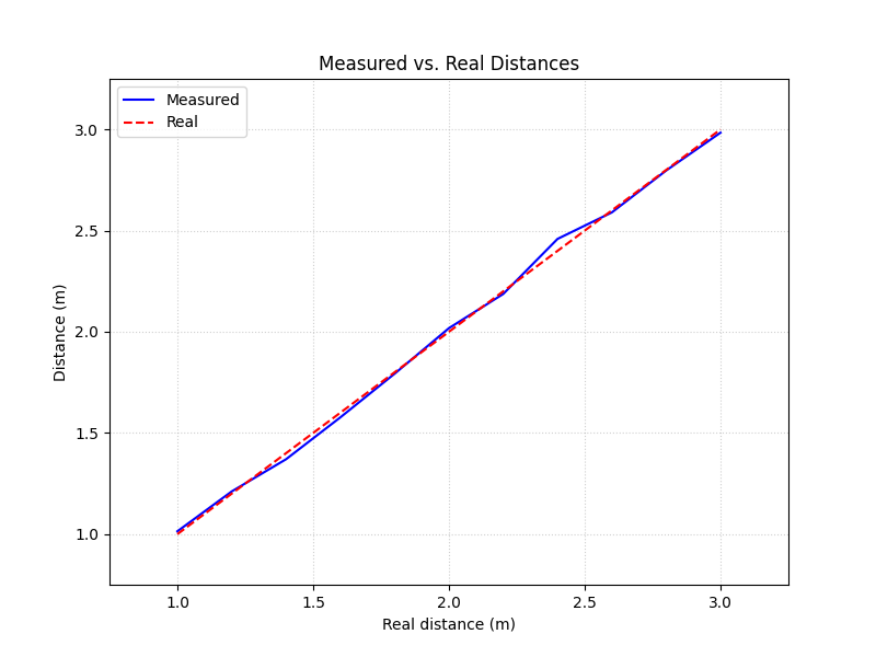
By performing SOL calibration using calibrated reference loads, and S21 through calibration, the radar system achieved a high degree of accuracy over the range of 1-3 meters. Since a wide range of sweep frequencies (2.00 GHz - 3.00 GHz) was used to simplify our testing, the maximum achievable distance was relatively short, but with a benefit to spatial resolution. The GUI allowed reconfiguring this on the fly.